Why FPV Antenna Choice Has More Impact on Flight Quality Than Most Pilots Expect
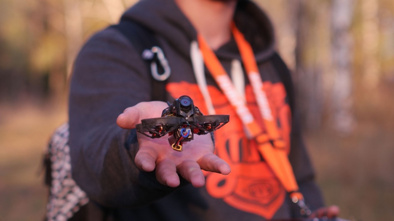
Most pilots building their first FPV quad spend the bulk of their budget on the flight controller, the motors, and the camera. The antenna gets whatever is left over, or whatever came bundled with the video transmitter. It works well enough on the bench, range tests look fine in the backyard, and then somewhere over an open field or through a patch of trees the feed stutters, pixelates, and cuts out entirely. The quad is fine. The vtx is fine. The antenna was the weak point.
The frustrating part is that this is predictable and avoidable. Antenna selection isn’t a particularly complicated subject, but the variables involved — gain, polarization, connector type, frequency matching — interact in ways that make a meaningful difference to real-world flight performance, not just to the numbers on a datasheet.
Gain: what it is and why more isn’t always better
Antenna gain describes how focused the antenna’s radiation pattern is. A high-gain antenna concentrates signal in a narrow cone — strong in one direction, weak everywhere else. A low-gain omnidirectional antenna spreads signal evenly in all directions around it, with less peak strength but consistent coverage regardless of where the quad is relative to the ground station.
For FPV flying, especially freestyle, racing, or any application where the aircraft’s orientation changes constantly, a highly directional antenna on the aircraft itself is counterproductive. The quad rolls, pitches, and yaws; the antenna points somewhere different every second. A high-gain directional antenna in that position will produce a strong signal when the beam happens to align with the ground station and a poor signal when it doesn’t.
On the ground station — the goggle or monitor side — a directional antenna with higher gain can improve range significantly because that antenna can be pointed at the aircraft and held there. The asymmetric approach (omnidirectional on the quad, higher-gain directional at the ground station) is the standard for good reason: it accounts for the different motion profiles on each end of the link.
Polarization and what happens when it’s mismatched
Antenna polarization describes the orientation of the electromagnetic wave the antenna transmits and receives. Linear polarization produces a wave that oscillates in one plane. Circular polarization produces a wave that rotates as it propagates — either left-hand circular (LHCP) or right-hand circular (RHCP).
The practical consequence for FPV: a linearly polarized signal loses up to 30dB when the transmitting and receiving antennas are oriented 90 degrees to each other. Because a flying quad is constantly changing its orientation, two linearly polarized antennas in an FPV system will cycle through optimal and worst-case alignment multiple times per second. The result is signal that fluctuates with the aircraft’s attitude rather than with distance.
Circular polarization eliminates this problem. An RHCP transmitting antenna paired with an RHCP receiving antenna maintains consistent signal strength regardless of how the quad is oriented, because the rotating wave field aligns regardless of physical rotation. The only rule is that both sides need to be the same handedness — RHCP to RHCP, or LHCP to LHCP. Mixing handedness produces roughly the same loss as a 90-degree linear mismatch.
This is why circular polarization has become standard for FPV video links. The consistency it provides across all flight attitudes is worth the small additional cost over basic linear antennas.
Frequency and the tradeoffs that come with it
FPV systems operate primarily on two frequency bands: 2.4GHz and 5.8GHz. The choice of frequency affects antenna size, signal behavior in different environments, and the compatibility of the antennas with the rest of the system.
5.8GHz is the more common band for analog FPV video. The shorter wavelength allows physically smaller antennas with adequate performance, which suits the weight and size constraints of racing and freestyle quads. 5.8GHz signals propagate well in open environments and carry video bandwidth cleanly. The limitation is penetration: higher frequencies lose more energy passing through obstacles, so thick vegetation, walls, and terrain features attenuate 5.8GHz signal more aggressively than lower frequencies.
2.4GHz offers better obstacle penetration at the cost of larger antenna size and more potential for interference from the crowded 2.4GHz band, which is also home to WiFi, Bluetooth, and many RC control links. Where 5.8GHz loses range in dense environments, 2.4GHz may hold the link longer. The tradeoff depends on the flying environment.
Matching the antenna to the frequency of the vtx or receiver is non-negotiable. An antenna designed for 5.8GHz has its physical dimensions tuned to resonate at that frequency. Using it at 2.4GHz doesn’t just underperform — it may present a significant impedance mismatch that reflects power back into the transmitter rather than radiating it.
Connector type and what gets overlooked
SMA and RP-SMA are the two connector standards most encountered in FPV. Standard SMA has a pin in the female connector; RP-SMA reverses this, with the pin in the male connector. They look similar, accept each other physically in some cases, but are electrically incompatible. Forcing a mismatched pair produces a connection with no center conductor contact — the system will transmit almost nothing while appearing connected.
This particular problem is common enough that it’s worth confirming connector type on both the vtx/rx and the antenna before purchasing. The confusion is compounded by the fact that different components in the same build sometimes use different standards, requiring adapters that introduce their own small signal losses.
TNC connectors, used on higher-power and professional-grade systems, offer better weatherproofing and lower loss at higher frequencies. For a fpv antenna going onto a system that will fly in variable weather or be connected and disconnected frequently, the mechanical durability of the connector matters alongside the RF specifications.
What this looks like in practice
A well-matched antenna setup for freestyle or racing FPV typically looks like this: circular polarization on both ends, matched handedness, 5.8GHz antennas matched to a 5.8GHz vtx, an omnidirectional or near-omnidirectional antenna on the quad, and a patch or helical antenna at the ground station for improved range. Total cost difference over a mismatched budget setup might be modest, but the difference in video feed consistency is substantial.
The antenna is where the signal either makes it from the air to your goggles or doesn’t. It’s worth treating it as a first-class component in the build, not an afterthought.